|
Bank Angle and the Physics of Standard Rate Turns (continued)
III - Obtaining an Exact Equation for the Bank Angle Required
for a Standard Rate Turn
Our goal, now that we understand the forces involved in the turn, is to obtain an exact equation. The input will be the aircraft's true airspeed (TAS) and output will be the bank angle  for standard rate turn. The technique to handle these types of problems, is to try to come up with equations that describe the geometry and physics. These equations are then combined in a way as to solve for the variables that were interested in. for standard rate turn. The technique to handle these types of problems, is to try to come up with equations that describe the geometry and physics. These equations are then combined in a way as to solve for the variables that were interested in.
Fig 3-1 Lift force, its components and relationship with the bank angle
Let's begin by examining how lift relates to the bank angle during our turn (see Fig 3-1).
Fig 3-2 The lift force and its components form a right triangle.
In figure 3-2, the side opposite to is equal to LH. Now we have a right triangle whose sides are L, LH and LV; with the angle between the sides with L and LV of .
Fig 3-3 Trigonometric solution to the right triangle
Rotate that triangle 90o clockwise and you can see that can be defined as the arctangent of LH over LV. This equation was derived from trigonometry and is our first equation. Note that this atan (arctangent) function is in radians not degrees.
As mentioned previously, the horizontal component of lift (LH) is the only force that does not cancel out with the others during the turn and is what makes the aircraft fly in a circle. From physics (laws of motion: centripetal force) we know that the force that causes an object to move in a circle is the centripetal force. It can be described by the following equation:
where CF is the centripetal force on the object, m is its mass, v is the speed of the object, and r is the radius of the circular path that the object is moving on. Since this force has to be equal to LH, we have:
Substituting LH for CF in equation  we have: we have:
We also know that the vertical component of lift (LV) equals the weight of the aircraft (W):
W can be defined by another equation from physics:
where W is the aircraft's weight, g is the acceleration of gravity, and m is its mass. We can substitute  in in  to get: to get:
Now we can substitute  and and  in in  and get: and get:
We are almost there. The mass "m" cancels out. The quantity v is the aircraft's speed, and we know that; "g" can be obtained easily from publications; however, "r" is not known.
We know that we are turning at a constant bank, speed and altitude. Turning also happens at a certain constant rate (3o per second for standard rate). This basically means that the heading will be changing at this rate, which we will call  (lowercase Greek omega). (lowercase Greek omega).
Fig 3-4 Aircraft flying in a circle - change in heading
We will also call  (lowercase Greek theta) the angle formed by the aircraft's position, the center of the circle and a fixed horizontal line passing through the center of the circle. From figure 3-4 note that a change in heading will correspond to the same change in . (lowercase Greek theta) the angle formed by the aircraft's position, the center of the circle and a fixed horizontal line passing through the center of the circle. From figure 3-4 note that a change in heading will correspond to the same change in .
Fig 3-5 Aircraft flying in a circle - angular speed and aircraft speed
The rate or speed that is changing is called angular speed. This is basically the rate of turn which we called . Not to be confused with the "v" in figure 3-5, which is the aircraft's speed. "v" can also be called tangential speed in this case since the aircraft is flying a circular path. S is the length of the circular path that the aircraft has already flown, however we will not need to use it in our formulas.
From physics (kinematics: angular speed) the radius "r" is a function of "v" and :
Great! We know and "v" so we can calculate the "r" that we needed in equation  . .
Now we can substitute  in and get: in and get:
This is the equation we wanted. However, it is not exactly ready for use by pilots yet. The units in the equations above must be consistent. To do that we have to pick a system of units. If the units we need are in a different system than the one we pick, then we must convert each different unit individually. Let's pick the International Standard of Units (SI) as our standard (see table 3-1 below).
Variables Used in Equation  in the in the
International Standard System of Units - SI Units |
| |
| Name |
Symbol |
SI Unit |
| Bank Angle |
 |
[rad] |
| Rate of Turn |
|
[rad/s] |
| Aircraft Speed |
v |
[m/s] |
| Acceleration of Gravity |
g |
[m/s2] |
 |
|
|
Table 3-1
Adapting the equation for units used in aviation
We will keep acceleration of gravity (g) in m/s2 since it is the most common unit for g. For the remaining units the table below gives each unit and the number that it has to be multiplied by for it to be converted to SI units and used in equation .
Variables Used in Equation in Units
Used in Aviation (Speed in Knots) |
| |
| Name |
Symbol |
Aviation Unit |
Multiplier to
Convert to SI |
Exact Conversion |
| Bank Angle |
|
[o] |
( /180) /180) |
yes |
| Rate of Turn |
|
[o/s] |
(/180) |
yes |
| Aircraft Speed |
v |
[knots] |
(463/900) |
yes |
|
|
|
Table 3-2
Applying all the conversion multipliers in equation we get:
| |
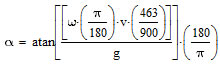 |
a |
|
Now let's use some more user-friendly names for the symbols:
| |
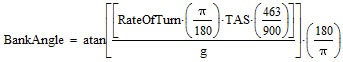 |
b |
|
Equation b is exact, however, at some point we will have to reduce this equation to something more usable. Substituting: the Rate of Turn = 3o/s for standard rate; using the conventional standard for g, which is 9.80665 m/s2; and evaluating up to 5 significant digits we get:
Bank Angle = 57.296 · atan (0.0027467 · TAS) c
Equation c gives the exact (with up to 5 significant digits of precision) bank angle in degrees for a standard rate turn. TAS is the true airspeed in knots. |